
It seems that every Christmas greets me (a bona fide railroad nut) with at least one question from a relative about the viability of high-speed rail. The answer is always the same: Depends on the population density and length scale (followed by the ability to secure a dedicated right-of-way). What follows are some numbers that show why we're still a long way from high-speed rail in other parts of this country.
Amtrak's Acela Express is the first high-speed rail in the US. It travels on a ROW largely designed by a private railroad in the 1950s. It attains speeds up to 155 mph and connects Washington, DC to Boston via Baltimore, Philadelphia, New York, New Haven, and Providence. Total distance: 308 miles. Total ridership: 3.4 million. Total profit: $178 million. (Note the $178 million profit number includes state subsidies)
The catch is that this train runs through the major population centers of the US: Washington/Baltimore - 9M, Philadelphia - 7M, New York/New Haven - 23M, Boston/Providence - 7.9M. I'm using Combined Statistical Area since the other statistics seem to have more overlap (i.e. double-counting of population). So the Acela runs 308 miles through a population of roughly 47M people (152,000 people per mile) and gets about 3.4 million to ride each year at a profit of $178 million per year.
The next two most-talked-about potential high-speed rail corridors are the Texas Corridor and the California Corridor.
The Texas Corridor is 240 miles and runs between Dallas (6.8M) and Houston (6.1M). That's only about 55,000 people per mile. If the $178M in "profit" (remember those subsidies) were scalable, the project could expect revenues in the ~$65M per year range. With a cost of $10 Billion, the simple payback on this project would be 154 years.
The California Corridor is 800 miles and runs between Sacramento (2.4M) and San Diego (3M) by way of San Francisco (8.1M) and Los Angeles (17.9M). That's only 40,000 people per mile...and you can see where this is going.
For comparison, projects in the private sector generally require 2-5 year simple paybacks. Federal projects want a 10 year simple payback at most. This Texas thing will prove to be a most interesting development. If they're able to make a go of it and things turn out better than I expect, high-speed rail might become a reality! (I'm not holding my breath, though...)
Saturday, December 27, 2014


Sunday, October 19, 2014
Inspirational Layout Themes
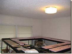
While I'd intended on posting a series of "Achievable Layout" themes, the timing of my posts shows that life gets in the way of my ability to blog. My layout is progressing...well, at least work on the layout room is progressing. I've got ceiling fans up, wiring for the layout lighting in place and a new ceiling put up in the layout room. With "modeling season" ahead, I plan on adding a floor to the layout room and begin getting benchwork in place.
Sadly, I still haven't settled on a plan or theme for my layout; something the "Achievable Layouts" series was supposed to help clarify. Since I cannot find the time to create separate posts for each theme, I'll just summarize the themes I had in mind here. Mike Cougill has written an interesting piece on how he selected his layout theme, which sort of spurred this post.
Theme 1 - Illinois Central Hickman District. The Hickman District ran 51 miles from Dyersburg, TN to Hickman, KY. Once out of Dyersburg, the line served several farming communities and a large cottonseed oil mill at Tiptonville, TN. Power for the line was IC #610, a little EMD SW-1. Today, the line still exists as the TennKen railroad. Were I to model this line, I'd focus on modeling Tiptonville as there wasn't much beyond this point on the line. The Obion River had a swing bridge that would make for a signature scene. Dyersburg would also make a neat town to model, but the IC had a double-track mainline through there, a mid-size yard with roundhouse and an interchange with the GM&O. It's a bit much to pull off in anything larger than N scale.
Theme 2 - Columbus & Greenville post-1975. The Columbus & Greenville covered 151 miles between its two namesake towns. After 1975 there were several changes that added and subtracted from that mileage, but the railroad managed to keep running between these two towns until a washout in 2001 severed service. There are several towns along the line worth modeling: Columbus, Greenville, Greenwood, Winona, and Indianola being the primary ones. The major industry on the line is the catfish feed mill at Heathman, MS (just west of Indianola). Only Winona and Indianola are truly manageable from a modeling standpoint. The CAGY spun up with a fleet of Baldwin DRS-6-4-1500s and EMD SW-1s, but added some ex-FEC GP-7s in 1978 and later added ex-Southern GP-9s, ex-CNW GP-7s and ex-Santa Fe CF-7s. Even later, more ex-Southern GP-38s rounded out the fleet.
Theme 3 - Bonhomie & Hattiesburg Southern. This line was bought by the Tatum Lumber Company when the M&O sought to abandon their Hattiesburg Branch. The B&HS was famous for running steam until 1961. When they dieselized, they did so with two ex-Wabash SW-1s. I know very little about the industries on this line, but there may not be much to know. When the line was absorbed by the Illinois Central Gulf merger in 1972, almost 70% of its traffic was overhead traffic.
Theme 4 - Fernwood, Columbia & Gulf. This line was built by the Enochs Lumber Company and ran between Fernwood, MS and Columbia, MS. Power came in the form of an EMD SW-900 and an SW-1 (starting to see a theme here?). The SW-900 was the "road power" while the SW-1 switched the mill in Fernwood. On heavy trains out of Fernwood, the little SW-1 would couple to the rear and push the train out of the Bogue Chitto River bottom. The line connected the IC at Fernwood to the GM&O at Tylertown and the IC and GM&O at Columbia. When the ICG merger was proposed, the line stood to lose 60% of its traffic. For me, a model of the FC&G would include Fernwood, Tylertown and the grade in-between.
Theme 5 - Meridian & Bigbee. This line was built in 1928 and connected Meridian, MS with Myrtlewood, AL; but never really amounted to much until the paper mill at Naheola,AL was built in 1957. The line dieselized with a GP-7 and a GP-9. They picked up an ex-IC GP-7 in 1964 and several more Geeps and a CF-7 in the 1970s and 80s. The railroad interchanged with the Southern, GM&O and IC at Meridian; the Frisco (AT&N) at Riderwood, AL and the L&N at Myrtlewood, AL. The signature scenes are the paper mill and one-lane highway/rail drawbridge at Naheola, the depot and interchange at Riderwood, and the yard at Meridian.
Theme 6 - Gulf & Mississippi. A 713-mile spinoff of the ICG, this railroad only lasted from 1985-1988. There's plenty of opportunities for modeling, but the areas that would interest me most would be Starkville, MS; the West Point-Aberdeen line; the operations around Corinth, MS and the Middleton, TN to Woodland, MS section that required trackage rights to reach. The railroad operated with 30 ex-ICG GP-10s (and maybe a few GP-8s), but leased ex-Conrail GP-38s and ex-BN SD-45s. Four of the GP-10s were repainted in a very attractive G&M paint scheme. The train that operated over trackage rights used a caboose.
Theme 7 - Mississippi Delta Railroad. This line was spun-off from the ICG in the mid-1980s and operated by Gulf & Ohio railways to serve the large cottonseed oil mill in Jonestown, MS. I think they handled some contract switching for ICG in Clarksdale as well when ADM's soybean oil mill was in operation and Cooper Tire shipped by rail. This line is still in existence, but is now owned by a rail cooperative and operated by an independent. In the 1980s, they used ex-ICG units, two GP-10s and a GP-8. Today, they use a couple of ex-C&G CF-7s. The cottonseed oil mill at Jonestown would be the signature industry to model on this line. Otherwise, a few of the industries at Clarksdale would be interesting to model, but the declining traffic on this line renders it just a switching railroad.
Theme 8 - Illinois Central at Helena, AR. This was IC's only track in Arkansas and operated until the 1970s via a ferry connection. This would essentially be a switching railroad, but would allow me to model the IC's river operations as well. Lack of information on the industries served as well as the status as a switching railroad have caused my interest to wane.
Theme 9 - Illinois Central at Grenada, MS. Grenada was still a hopping place post-1967. IC still ran two passenger trains through town (the Panama Limited and City of New Orleans), but no through freights unless they were detouring off the Tallahatchie District. However, Grenada was the terminus for the Grenada-Durant turn, the Memphis-Grenada turn, and had a Water Valley-Canton local (41/42) that came through town but only stopped to pick up cuts of cars. A switcher worked a yard north of town, a few industries in-town and along an old Y&MV branch line. Train interactions would be THE attraction to Grenada. I've spent some time designing a layout to depict Grenada, but it's almost impossible to fit everything in HO scale, much less my preferred S scale. Not to mention the amount of equipment needed to pull this one off!
Theme 10 - Memphis Parkway Yard. This yard served the adjacent Ford Motor Company assembly plant, International Harvester and General Electric. Additionally, there were multiple small industries that shipped by rail. The line was switched by reciprocal agreement between the Illinois Central, Missouri Pacific, Cotton Belt and Frisco on quarterly shifts. The Illinois Central covered Cotton Belt's portion of the agreement, meaning you had six months of IC and three months of Mop and Frisco. This would be an all-switching layout and an intercity one at that. While I do call Memphis my hometown and the opportunity to model three railroads is tempting, I can't bring myself to build a layout that wouldn't have any trees. Sure, I could fudge a sapling in here or there, but this was down-and-dirty city railroading.
Theme 11 - Mississippi & Skuna Valley. The little line was owned by the Bruce Lumber Company (later Weyerhaeuser) and ran from Bruce Junction (just south of Coffeeville) to Bruce, MS. The line operated with a 70-tonner in the early 1970s, picked up an ex-Penn Central SW-9 and an ex-Santa Fe CF-7 which it used until abandonment in 2011. The major customer was the Weyerhaeuser, but the line also served a furniture plant, a propane dealer and a grain silo in Bruce. Otherwise, there were no other industries on the line. This would essentially be a switching railroad centered on Bruce, MS.
Those eleven themes all have their strong points and negative points. The trick for me is to determine what elements of these themes cause me to want to model them. Perhaps the answer of "What to model?" is not a matter of picking a single theme, but combining elements of multiple themes in a plausible way. Any thoughts you have would be appreciated!!
Sadly, I still haven't settled on a plan or theme for my layout; something the "Achievable Layouts" series was supposed to help clarify. Since I cannot find the time to create separate posts for each theme, I'll just summarize the themes I had in mind here. Mike Cougill has written an interesting piece on how he selected his layout theme, which sort of spurred this post.
Theme 1 - Illinois Central Hickman District. The Hickman District ran 51 miles from Dyersburg, TN to Hickman, KY. Once out of Dyersburg, the line served several farming communities and a large cottonseed oil mill at Tiptonville, TN. Power for the line was IC #610, a little EMD SW-1. Today, the line still exists as the TennKen railroad. Were I to model this line, I'd focus on modeling Tiptonville as there wasn't much beyond this point on the line. The Obion River had a swing bridge that would make for a signature scene. Dyersburg would also make a neat town to model, but the IC had a double-track mainline through there, a mid-size yard with roundhouse and an interchange with the GM&O. It's a bit much to pull off in anything larger than N scale.
Theme 2 - Columbus & Greenville post-1975. The Columbus & Greenville covered 151 miles between its two namesake towns. After 1975 there were several changes that added and subtracted from that mileage, but the railroad managed to keep running between these two towns until a washout in 2001 severed service. There are several towns along the line worth modeling: Columbus, Greenville, Greenwood, Winona, and Indianola being the primary ones. The major industry on the line is the catfish feed mill at Heathman, MS (just west of Indianola). Only Winona and Indianola are truly manageable from a modeling standpoint. The CAGY spun up with a fleet of Baldwin DRS-6-4-1500s and EMD SW-1s, but added some ex-FEC GP-7s in 1978 and later added ex-Southern GP-9s, ex-CNW GP-7s and ex-Santa Fe CF-7s. Even later, more ex-Southern GP-38s rounded out the fleet.
Theme 3 - Bonhomie & Hattiesburg Southern. This line was bought by the Tatum Lumber Company when the M&O sought to abandon their Hattiesburg Branch. The B&HS was famous for running steam until 1961. When they dieselized, they did so with two ex-Wabash SW-1s. I know very little about the industries on this line, but there may not be much to know. When the line was absorbed by the Illinois Central Gulf merger in 1972, almost 70% of its traffic was overhead traffic.
Theme 4 - Fernwood, Columbia & Gulf. This line was built by the Enochs Lumber Company and ran between Fernwood, MS and Columbia, MS. Power came in the form of an EMD SW-900 and an SW-1 (starting to see a theme here?). The SW-900 was the "road power" while the SW-1 switched the mill in Fernwood. On heavy trains out of Fernwood, the little SW-1 would couple to the rear and push the train out of the Bogue Chitto River bottom. The line connected the IC at Fernwood to the GM&O at Tylertown and the IC and GM&O at Columbia. When the ICG merger was proposed, the line stood to lose 60% of its traffic. For me, a model of the FC&G would include Fernwood, Tylertown and the grade in-between.
Theme 5 - Meridian & Bigbee. This line was built in 1928 and connected Meridian, MS with Myrtlewood, AL; but never really amounted to much until the paper mill at Naheola,AL was built in 1957. The line dieselized with a GP-7 and a GP-9. They picked up an ex-IC GP-7 in 1964 and several more Geeps and a CF-7 in the 1970s and 80s. The railroad interchanged with the Southern, GM&O and IC at Meridian; the Frisco (AT&N) at Riderwood, AL and the L&N at Myrtlewood, AL. The signature scenes are the paper mill and one-lane highway/rail drawbridge at Naheola, the depot and interchange at Riderwood, and the yard at Meridian.
Theme 6 - Gulf & Mississippi. A 713-mile spinoff of the ICG, this railroad only lasted from 1985-1988. There's plenty of opportunities for modeling, but the areas that would interest me most would be Starkville, MS; the West Point-Aberdeen line; the operations around Corinth, MS and the Middleton, TN to Woodland, MS section that required trackage rights to reach. The railroad operated with 30 ex-ICG GP-10s (and maybe a few GP-8s), but leased ex-Conrail GP-38s and ex-BN SD-45s. Four of the GP-10s were repainted in a very attractive G&M paint scheme. The train that operated over trackage rights used a caboose.
Theme 7 - Mississippi Delta Railroad. This line was spun-off from the ICG in the mid-1980s and operated by Gulf & Ohio railways to serve the large cottonseed oil mill in Jonestown, MS. I think they handled some contract switching for ICG in Clarksdale as well when ADM's soybean oil mill was in operation and Cooper Tire shipped by rail. This line is still in existence, but is now owned by a rail cooperative and operated by an independent. In the 1980s, they used ex-ICG units, two GP-10s and a GP-8. Today, they use a couple of ex-C&G CF-7s. The cottonseed oil mill at Jonestown would be the signature industry to model on this line. Otherwise, a few of the industries at Clarksdale would be interesting to model, but the declining traffic on this line renders it just a switching railroad.
Theme 8 - Illinois Central at Helena, AR. This was IC's only track in Arkansas and operated until the 1970s via a ferry connection. This would essentially be a switching railroad, but would allow me to model the IC's river operations as well. Lack of information on the industries served as well as the status as a switching railroad have caused my interest to wane.
Theme 9 - Illinois Central at Grenada, MS. Grenada was still a hopping place post-1967. IC still ran two passenger trains through town (the Panama Limited and City of New Orleans), but no through freights unless they were detouring off the Tallahatchie District. However, Grenada was the terminus for the Grenada-Durant turn, the Memphis-Grenada turn, and had a Water Valley-Canton local (41/42) that came through town but only stopped to pick up cuts of cars. A switcher worked a yard north of town, a few industries in-town and along an old Y&MV branch line. Train interactions would be THE attraction to Grenada. I've spent some time designing a layout to depict Grenada, but it's almost impossible to fit everything in HO scale, much less my preferred S scale. Not to mention the amount of equipment needed to pull this one off!
Theme 10 - Memphis Parkway Yard. This yard served the adjacent Ford Motor Company assembly plant, International Harvester and General Electric. Additionally, there were multiple small industries that shipped by rail. The line was switched by reciprocal agreement between the Illinois Central, Missouri Pacific, Cotton Belt and Frisco on quarterly shifts. The Illinois Central covered Cotton Belt's portion of the agreement, meaning you had six months of IC and three months of Mop and Frisco. This would be an all-switching layout and an intercity one at that. While I do call Memphis my hometown and the opportunity to model three railroads is tempting, I can't bring myself to build a layout that wouldn't have any trees. Sure, I could fudge a sapling in here or there, but this was down-and-dirty city railroading.
Theme 11 - Mississippi & Skuna Valley. The little line was owned by the Bruce Lumber Company (later Weyerhaeuser) and ran from Bruce Junction (just south of Coffeeville) to Bruce, MS. The line operated with a 70-tonner in the early 1970s, picked up an ex-Penn Central SW-9 and an ex-Santa Fe CF-7 which it used until abandonment in 2011. The major customer was the Weyerhaeuser, but the line also served a furniture plant, a propane dealer and a grain silo in Bruce. Otherwise, there were no other industries on the line. This would essentially be a switching railroad centered on Bruce, MS.
Those eleven themes all have their strong points and negative points. The trick for me is to determine what elements of these themes cause me to want to model them. Perhaps the answer of "What to model?" is not a matter of picking a single theme, but combining elements of multiple themes in a plausible way. Any thoughts you have would be appreciated!!
Saturday, September 14, 2013
Texas Transportation Company
The first idea for an achievable layout is the Texas Transportation company. This 1.3-mile electric traction freight line served the Pearl Brewery in San Antonio, TX until 2001. This line remained an electric traction operation throughout its history on account of the city wanting to remove its tracks down the middle of Jones Avenue. If the line had converted to diesels, the city could have forced the railroad to remove the track.
Here's a few photos and video to get you going:
TXTC#1
TXTC#2
Don Ross's site
Video 1
Video 2
From what I can tell, it looks like they had inbound loads of corn syrup, hops and probably some packaging materials. Beer is the most obvious outbound load, but apparently the local glass company shipped a load of plate glass from time-to-time. The signature structures along this line would have to be the Pearl Brewery building (with rotating sign), the Pearl stable building (the oval building in the photos), and the Pearl bottle houses (the two buildings that form the alleyway in this photo). From the brewery, the railroad ran down the middle of Jones Avenue alongside the old Lone Star Brewery, which has housed the San Antonio Museum of Art since the 1970s. The last signature structure would be the truss bridge that spans the SP-TXTC interchange tracks.
If I were to model this railroad, I'd set it in the 1990s and do it along three walls. From left-to-right going around the room: The first wall would be the SP interchange with the bridge and a few warehouses/industries along the backdrop. At one time (1960s and earlier?), these industries were served by the traction railroad. If I wanted to add a little more operation, I might add a few car spots to the interchange track nearest the buildings. The second wall would be street running down Jones Avenue. The Hwy 281 overpass would form the left boundary of this scene. I'd want the old Lone Star Brewery structure to form the backdrop, so I'd use a little modeler's license there to orient that structure along the backdrop. The third wall would be the Pearl Brewery scene. The I-35 overpass would form the left boundary of this scene. The tracks would immediately duck into the bottling plant area and come out into the brewery scene. One of the best things about this line is that a 24" radius in HO scale would be prototypically sharp!
A model appropriate for TXTC #1 has been made in almost every scale (including S!). TXTC #2 would have to be scratchbuilt. The rest of the freight car roster could be fleshed out using commercially available kits. Since the SP was the connecting railroad, plenty of options are available in all scales.
The railroad switched the brewery at least twice per day. I could definitely see inviting a few guys over and enjoying some switching operations while partaking a bit of the ladings! I wonder if I can find Pearl Beer in Alabama?
Here's a few photos and video to get you going:
TXTC#1
TXTC#2
Don Ross's site
Video 1
Video 2
From what I can tell, it looks like they had inbound loads of corn syrup, hops and probably some packaging materials. Beer is the most obvious outbound load, but apparently the local glass company shipped a load of plate glass from time-to-time. The signature structures along this line would have to be the Pearl Brewery building (with rotating sign), the Pearl stable building (the oval building in the photos), and the Pearl bottle houses (the two buildings that form the alleyway in this photo). From the brewery, the railroad ran down the middle of Jones Avenue alongside the old Lone Star Brewery, which has housed the San Antonio Museum of Art since the 1970s. The last signature structure would be the truss bridge that spans the SP-TXTC interchange tracks.
If I were to model this railroad, I'd set it in the 1990s and do it along three walls. From left-to-right going around the room: The first wall would be the SP interchange with the bridge and a few warehouses/industries along the backdrop. At one time (1960s and earlier?), these industries were served by the traction railroad. If I wanted to add a little more operation, I might add a few car spots to the interchange track nearest the buildings. The second wall would be street running down Jones Avenue. The Hwy 281 overpass would form the left boundary of this scene. I'd want the old Lone Star Brewery structure to form the backdrop, so I'd use a little modeler's license there to orient that structure along the backdrop. The third wall would be the Pearl Brewery scene. The I-35 overpass would form the left boundary of this scene. The tracks would immediately duck into the bottling plant area and come out into the brewery scene. One of the best things about this line is that a 24" radius in HO scale would be prototypically sharp!
A model appropriate for TXTC #1 has been made in almost every scale (including S!). TXTC #2 would have to be scratchbuilt. The rest of the freight car roster could be fleshed out using commercially available kits. Since the SP was the connecting railroad, plenty of options are available in all scales.
The railroad switched the brewery at least twice per day. I could definitely see inviting a few guys over and enjoying some switching operations while partaking a bit of the ladings! I wonder if I can find Pearl Beer in Alabama?
Monday, September 9, 2013
Achievable Layouts, Southern Style
So it's been a while since I've posted here. We've moved three times, renovated two houses and had two more children in that span. I hope you'll give me a flyer on missing a few blog postings.
Trevor Marshall's new blog on Achievable Layouts has inspired me to blog about a few layout themes that I have contemplated over the last few years. Trevor's blog has several Canadian themes, which sort of makes sense given that Trevor's Canadian. I thought it might be time to add a few layout themes from my neck of the woods. I plan on mixing this in with a few layout construction posts. I'd originally intended on the blog being something that would keep my modeling efforts on-track...so let's see if I can get this thing re-railed!
Stay tuned for the first of my own "achievable layouts"...
Sunday, January 10, 2010
Over-Center Springs for Atlas Code 55 Turnouts
The lack of blog activity is due to progress on the layout. I really have trouble blogging and building at the same time…I’m just glad that progress is being made! I’ve laid all of the roadbed and built all of the trestle bents, so the next task is to get the track laid. Before I can do this, though, I needed to come to some conclusion regarding control of my Atlas code 55 turnouts.
When it comes to turnout control, there’s a whole host of ways to accomplish the task: Tortoise machines, servos, ground throws, latch-bolt throws, solenoid machines, finger-flick, pushrods…and then there’s the combinations of these methods! To simplify things, I like to categorize these in terms of Electronic vs. Manual and Under-table vs. Topside-mount. Here’s the breakdown on how those technologies fit into my grid:
Currently, I cannot afford the electronic options, so cancel out that column of options. Since my layout is movable, I’m not real keen on mounting things beneath the layout. Too much chance of something getting snagged during a move and a pain to adjust when things shift after a move. So scratch off the row of under-table options. That leaves Caboose Industries ground throws, electric toggles with pushrods, and the finger-flick method.
I initially bought some Caboose Industries ground throws, but their large size compromised the appearance of the code 55 track. Why go to the trouble of near-scale track only to butcher the look with an oversize ground throw? I would have been better off to use Peco code 55 and lived with the European tie spacing. While there have been some really good ideas to disguise the CI throw’s oversize appearance, I didn’t think this would work since my spline roadbed would basically leave the throws unsupported. I tried using electric toggle switches with linkages on my test bed layout. While simple enough, I’ve had some problems with the toggle throw being longer than the turnout throw. The turnouts on my test bed layout were soldered together, so they were able to handle the stress. I feared that the Atlas code 55 turnouts might not fare so well and there’s still that whole mounting thing. That left me with the finger-flick method with either a center-over spring or a friction pad. I tried doing a friction pad on the bottom of the throwbar, but worries of what would happen once the friction pad wore down kept me from pursuing this route. Still the friction pad is a great idea and is probably something I’ll consider again.
So a center-over spring it is! Atlas code 55 turnouts, unlike their Peco and Micro Engineering counterparts, do not have a center-over spring. No problem. I’ll just make one. Surely someone on the internet has a “how-to” to guide me. A search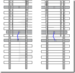 revealed some verbal descriptions on a blog, but no pictures. I know it’s just three bends in a piece of wire, but someone should really do a video or something. For now, the diagram to the left will have to do. The idea is simple: moving the turnout from right to left causes compression in the spring (the blue line) until the throw reaches the midpoint. At the midpoint, the spring is under maximum compression. Further movement to the left will release compression on the spring, causing the points to snap to the left when the throw reaches the midpoint. The same compression occurs as the points are moved back to the right, causing the points to snap to the right once the throw moves past the midpoint on the right side. Since the compression tends to release itself once the throw is moved “over the center point,” these devices are called “over-center springs" or "center-over springs.” Below is a YouTube video on how I made center-over springs for my Atlas turnouts.
When it comes to turnout control, there’s a whole host of ways to accomplish the task: Tortoise machines, servos, ground throws, latch-bolt throws, solenoid machines, finger-flick, pushrods…and then there’s the combinations of these methods! To simplify things, I like to categorize these in terms of Electronic vs. Manual and Under-table vs. Topside-mount. Here’s the breakdown on how those technologies fit into my grid:
| Electronic | Manual | |
| Under-table |
|
|
| Topside Mount |
|
|
I initially bought some Caboose Industries ground throws, but their large size compromised the appearance of the code 55 track. Why go to the trouble of near-scale track only to butcher the look with an oversize ground throw? I would have been better off to use Peco code 55 and lived with the European tie spacing. While there have been some really good ideas to disguise the CI throw’s oversize appearance, I didn’t think this would work since my spline roadbed would basically leave the throws unsupported. I tried using electric toggle switches with linkages on my test bed layout. While simple enough, I’ve had some problems with the toggle throw being longer than the turnout throw. The turnouts on my test bed layout were soldered together, so they were able to handle the stress. I feared that the Atlas code 55 turnouts might not fare so well and there’s still that whole mounting thing. That left me with the finger-flick method with either a center-over spring or a friction pad. I tried doing a friction pad on the bottom of the throwbar, but worries of what would happen once the friction pad wore down kept me from pursuing this route. Still the friction pad is a great idea and is probably something I’ll consider again.
So a center-over spring it is! Atlas code 55 turnouts, unlike their Peco and Micro Engineering counterparts, do not have a center-over spring. No problem. I’ll just make one. Surely someone on the internet has a “how-to” to guide me. A search
 revealed some verbal descriptions on a blog, but no pictures. I know it’s just three bends in a piece of wire, but someone should really do a video or something. For now, the diagram to the left will have to do. The idea is simple: moving the turnout from right to left causes compression in the spring (the blue line) until the throw reaches the midpoint. At the midpoint, the spring is under maximum compression. Further movement to the left will release compression on the spring, causing the points to snap to the left when the throw reaches the midpoint. The same compression occurs as the points are moved back to the right, causing the points to snap to the right once the throw moves past the midpoint on the right side. Since the compression tends to release itself once the throw is moved “over the center point,” these devices are called “over-center springs" or "center-over springs.” Below is a YouTube video on how I made center-over springs for my Atlas turnouts.
Saturday, November 14, 2009
DCC Controls for the HOG
Among all of the construction decisions, I've been contemplating how I'm going to control this layout. DCC is a foregone conclusion as it's the best way to get control of the locomotive (and all of my locomotives are already DCC-equipped). I've got a Digitrax Radio Super Chief that I purchased with the intention of using with an N-trak group (more on that below), but this system is overkill for a layout of this size and the only other modeler in my local area is an NCE user. The NCE PowerCab is the best option for a layout of this size, but my wife is liking the idea of using her iPod Touch as a throttle, so the ESU Ecos system has been getting alot of looks as well.... The Digitrax Radio Super Chief is a fantastic system, and when I bought it, I had several HO locomotives that had all of the bells and whistles (or the sounds, at least) and I needed the many, many functions that the Digitrax DT400R could perform. I've since sold this HO equipment and my N scale equipment doesn't need such a fancy control system. However, I noticed that many of the Ntrak clubs in the Dallas-Fort Worth area were avid Digitrax users and the Super Chief makes a nice system for an N-trak club. With that in mind, I built an "N-trak box". Here's what it looks like:


The box is built out of aspen plywood and measures 19" x 10" x 10". While there may be some wasted space, it ain't much! The top photo shows the front of the box. On the front is a lockable case latch so a small padlock can be applied to the case to keep little hands out when it's time to go to lunch or peruse the train show. The second photo shows the end where a large computer fan draws in air and pushes it across the transformers and the booster. On the backside (third photo), you can see the piano case hinge for the box lid, the exit hole for the cooling air, and the standard computer plug that connects to the power supply. Using the removable power cord makes it very easy to transport. The last picture shows the business end with the Digitrax UR91 radio throttle receiver and four Cinch-Jones plugs. The Cinch-Jones connectors are the Ntrak standard, so this box can quickly be connected to any Ntrak layout.


Opening the box, there's a programming track and a tray to hold all of the throttles, power cable, and connector cable. This tray is also a safeguard against curious little hands that might find their way into the box.

Removal of the tray reveals the guts of the system: The DCS100 booster, the UR91 radio throttle receiver, and the PM42 power manager (all on the right). The booster is attached with heavy-duty velcro just in case it needs to be removed. The UR91 allows Digitrax simplex radio throttles to be used. The PM42 is particularly necessary for Ntrak layouts since it allows individual circuit breaker detection. This way, a short on one track doesn't cause a system crash and everyone else can keep running trains while the short is found. On the left, there are a couple of fuses and a circuit breaker for the power supply. Just plugging in the power cord does not power up the transformers. The switch on the far left has to be thrown first. Even that does not power up the booster; that's the purpose of the other switch. All exposed wiring on the right side of the box is either 12V or 16V, so there's no real shock hazard. Even at this level, I didn't want there to be any chance of a child getting shocked. Hopefully, someone will have spotted the little tike by the time he/she gets this far!!

Removing the partition and lifting the cover that contains the power switches and the circuit breakers shows the transformers. The terminal blocks on the left carry 110V power, so it's a good idea to have the box unplugged before even opening this side. The fan is a 110V fan, so it runs directly off the input power. The large transformer powers the booster, while the two smaller transformers provide power to the UR91 and the PM42.
And that's it! All in all, it's about the best way I've seen to make a full DCC system truly portable. Putting the system in a box sure cuts down on the clutter associated with the Digitrax system, so this might be a good idea for any Digitrax user. I hope these ideas are of some use to you...


The box is built out of aspen plywood and measures 19" x 10" x 10". While there may be some wasted space, it ain't much! The top photo shows the front of the box. On the front is a lockable case latch so a small padlock can be applied to the case to keep little hands out when it's time to go to lunch or peruse the train show. The second photo shows the end where a large computer fan draws in air and pushes it across the transformers and the booster. On the backside (third photo), you can see the piano case hinge for the box lid, the exit hole for the cooling air, and the standard computer plug that connects to the power supply. Using the removable power cord makes it very easy to transport. The last picture shows the business end with the Digitrax UR91 radio throttle receiver and four Cinch-Jones plugs. The Cinch-Jones connectors are the Ntrak standard, so this box can quickly be connected to any Ntrak layout.


Opening the box, there's a programming track and a tray to hold all of the throttles, power cable, and connector cable. This tray is also a safeguard against curious little hands that might find their way into the box.

Removal of the tray reveals the guts of the system: The DCS100 booster, the UR91 radio throttle receiver, and the PM42 power manager (all on the right). The booster is attached with heavy-duty velcro just in case it needs to be removed. The UR91 allows Digitrax simplex radio throttles to be used. The PM42 is particularly necessary for Ntrak layouts since it allows individual circuit breaker detection. This way, a short on one track doesn't cause a system crash and everyone else can keep running trains while the short is found. On the left, there are a couple of fuses and a circuit breaker for the power supply. Just plugging in the power cord does not power up the transformers. The switch on the far left has to be thrown first. Even that does not power up the booster; that's the purpose of the other switch. All exposed wiring on the right side of the box is either 12V or 16V, so there's no real shock hazard. Even at this level, I didn't want there to be any chance of a child getting shocked. Hopefully, someone will have spotted the little tike by the time he/she gets this far!!

Removing the partition and lifting the cover that contains the power switches and the circuit breakers shows the transformers. The terminal blocks on the left carry 110V power, so it's a good idea to have the box unplugged before even opening this side. The fan is a 110V fan, so it runs directly off the input power. The large transformer powers the booster, while the two smaller transformers provide power to the UR91 and the PM42.
And that's it! All in all, it's about the best way I've seen to make a full DCC system truly portable. Putting the system in a box sure cuts down on the clutter associated with the Digitrax system, so this might be a good idea for any Digitrax user. I hope these ideas are of some use to you...
Saturday, November 7, 2009
Adding the Fascia
Once the glueshell dried, I measured from the bottom of the benchwork to the top of the glueshell scenery at the layout edges. Just under 6” was the longest measurement, so I cut a 4x8 sheet of Masonite into 6” strips and attached them to the sides of the layout with clamps to temporarily hold them in place. Using a felt pen, I marked off the land contours by tracing along the joint between the glueshell and the fascia board. Cutting along the lines with a jigsaw yielded a nice fascia piece that matched to land contours:

You can see the holes that were drilled to allow the clamping bolts to pass through. I forgot to do this on one section before I attached them to the layout. Let’s just say that it really helps to pay attention to detail at this point! Once the contours were shaped, it was time to attach them to the layout with wood glue and clamps:


You’ll notice that I let the ends hang out over the corners of each layout section. These can be cleaned up with a flush-trim bit in a Roto-Zip after the glue dries.

One advantage of allowing the ends to hang out a bit is that you have a surface to leverage if the corners don’t come out EXACTLY square. I had this happen on the end piece in the photo below where I was lacking a 1/16” being flush with the adjacent piece at the corner. Using a bungee strap and the weight of the layout, I was able to pull against those long ends to take that 1/16” out and get a nice, flush fit:

After trimming with the Roto-Zip, here’s the layout with the fascia installed:


I also had to do a bit of cleanup with the flush-trim bit at the layout joints since some of my marks didn’t match up exactly. If you haven’t used one of these bits in a Roto-Zip or a router, they make quick work of the problem of cutting a corner piece exactly to length. I highly recommend giving one a try!
Glue Shell Scenery – Comments now that it’s dried…
In my last post, I only had one layer of glueshell scenery down and I was switching from diluted ModPodge to full-strength Elmer’s GlueAll. My hope was that the full-strength Glue-All, coupled with the second layer of paper, would create a nice rigid scenery shell. Unfortunately, that plan didn’t come together exactly like I’d hoped! The full-strength GlueAll is still pretty rubbery, flexible stuff after it dries. The second layer of paper did help to make things a bit more rigid, but not nearly as hard as a plaster shell. This can be a good thing, though. My layout is intended to be semi-portable. Scenery that has some give to it will be less likely to be punctured or cracked as things get moved around.
I had some places where the paper shrunk as it dried, which created some interesting landforms. By far, the glueshell did the best job in the places where it was well-supported by the benchwork. It’s not a good idea to try to cover vast expanses of unsupported areas with cheesecloth, paper and glue. If you’ve got this situation, either use a stiffer plastic or even metal screen in place of the cheesecloth or use a stiffer medium than the glue (plaster is a good example). Hindsight being 20/20, I really wished I’d used undiluted PVA (wood glue) as my medium throughout. It’s $30 a gallon at the local big box store, but it dries much stiffer than either ModPodge or GlueAll.
Good news is, I’ve got the opportunity to give this a try: I’ll be using Titebond 3 to attach the glueshell to the fascia; an area where a good, stiff connection is critical. I’ll let you know the outcome. I still love the glueshell scenery and I’ll continue to use it, but I did learn a lesson about unsupported scenery this time around…
Been a while….
I had originally thought that this blog would be a great way to 1) share my experiences in model railroading and 2) to keep myself moving forward on the railroad since folks might be following along. The reality is that blogging takes some work to be worth a flip. You need pictures that are of decent quality and help tell the story. Unless you’re like my sister-in-law, you also need time to think through the post and to write it well. The aforementioned sister-in-law is able to put together well-written posts in a matter of 30 minutes or so…I just don’t have her verbal skills!
SO…rather than spend an inordinate amount of time blogging, I decided to focus my efforts on getting the layout done. Since the last post, I’ve laid up another layer of glueshell scenery using full-strength Elmer’s GlueAll, added the layout fascia, laid the cork roadbed, made some decision regarding turnout linkages and begun to solder together some of the “turnout junctions.” I’ll address the outcomes of each of these activities in separate posts (to make them easier to follow). The great thing about this approach is that my modeling time is put to maximum effect and progress is made. The bad thing about this approach is that my blog goes long periods without being updated. I’d rather have a model railroad than a really nice blog, so the trade-off has been a good one…
Sunday, August 2, 2009
Glue Shell Scenery
I know it's been a while since I've posted here. That's 'cause I've been working on the layout!! Here's a few shots with the styrofoam supports cut to fit around the spline roadbed:

I wanted a spot where a local highway passed under the track. This meant cutting through the spline roadbed and supporting the spline with plywood. Unfortunately, the spline was only a scale 12' tall, so I had to drop the roadbed support a bit and shim to the underside of the spline. You can see the shims on top of the 3/4" plywood on the right. The best part was that this construction created a nice dip in the highway, which is built from a 1/8" piece of lauan plywood.


I wanted a spot where a local highway passed under the track. This meant cutting through the spline roadbed and supporting the spline with plywood. Unfortunately, the spline was only a scale 12' tall, so I had to drop the roadbed support a bit and shim to the underside of the spline. You can see the shims on top of the 3/4" plywood on the right. The best part was that this construction created a nice dip in the highway, which is built from a 1/8" piece of lauan plywood.

For the landforms, I tried my hand at my version of Howard Zane's glue shell scenery base. Howard uses red rosin paper and straight white glue. I used brown kraft paper cut into strips and dipped them in a 1:1 mixture of water and matte medium (Mod-Podge). I didn't have a good source for large quantities of white glue, and I know that acrylic matte medium is plenty hard when it dries. But at $7.50 per bottle, I figured I could get away with diluting the matte medium to spread it a little further. More on this later. The soaked strips were draped over the spline roadbed and foam pieces that formed the basic landscape. It's alot like working with wallpaper. The end result can be seen below:

Okay...so that one still has some spots that need to be touched up. I used a very light cheesecloth to cover large open areas between the foam hill supports. I really like the way that I could form ditches along the ROW in the cut.
The area shown below will be a swampy area just on the outskirts of town. I used a strip of plywood to support the spline roadbed where I had to make the cutout for a trestle. A couple of carefully-placed styrofoam sheets created a dead-flat surface which will ultimately be covered with Enviro-Tex "water".

And here's the shot of that highway scene again.

So far, I love the glueshell scenery. It goes fast and isn't too messy, especially with the $3 drop cloth underneath to catch anything that drops through. You do need to figure on a good 10 minutes to clean the dried acrylic off your hands at the end of laying it up, but it's much less mess than cutting styrofoam. When the Mod-Podge dries, I'm left with a firm-yet-flexible scenery base...not as firm as I'd hoped for, but perfect for a portable layout!!
On a trip to Lowe's this evening, I spied a gallon jug (128 fl.oz.) of Elmer's Glue All for around $11. I had spent $15 on 32 ounces of Mod-Podge and had to dilute it. I've got a small amount of Glue All that I plan to use undiluted to do a few of the remaining sections. My guess is that the full-strength Glue All will create a more rigid base. If so, I'll be using Glue All instead of Mod-Podge in the future to save on the expense.
In other news, our local Wal-Mart now has RC's in the dispensing machines out front for $0.75.... :-)

Tuesday, June 23, 2009
Still Kicking
I know it’s been a while since I’ve posted. School and work have kept me plenty busy, so what time I have for model railroading I’ve chosen to spend model railroading instead of blogging. I’ve managed to finally fix the driveshaft issues with my Overland N scale SD70s, get the exposed wood on the benchwork covered with a nice coat of latex paint, cut out the foam supports for the town areas of the layout, and I’ve finished one N scale structure kit. It’s really amazing what you can get done if you stop thinking and get to doing. I thought the blog would help me to keep at my hobby, but I’m enjoying the hobby so much there’s no time to blog. While that’s not exactly how I thought it would work, the end goal (modeling) has been achieved and for that I’m glad. More to follow (hopefully soon)…
Tuesday, February 17, 2009
Coming Together

So my version of the HOG layout is finally coming together. I decided to use 54" shelving units for my layout support since they'd be sturdy and would create ready-made storage space under the layout. These shelving units are normally found at Target, but we have a store here in town that gets damaged lots from Target and sells them at a greatly reduced price: Hudson's Dirt Cheap. We'd found one of these units a few months back, but it took us several more weeks of scrounging the local Dirt Cheap stores to find the next two. But at $15 apiece, it was worth the wait!

With the supports purchased, it was time to put the layout together. I was extremely pleased with the way my workbench fits underneath. I added a couple of photos to show how the layout height appears to me (6'1") and to my wife (5'4"). All in all, the layout height couldn't have been better. Now it's time to paint that benchwork to keep it from swelling (currently in process) and then it'll be time to rough in some scenery! More photos of my progress can be found here.

Sunday, February 1, 2009
Eritrea's Railways
Wanna know where you can see narrow gauge articulated steam locomotives in action in 2008? Check out the Eritrean Railway (1 hour video):
Thursday, January 22, 2009
Layout Tours
So this past weekend, my wife and I loaded up our car and headed to Plano, TX for the North Texas Council's annual Plano Train Show. The show featured more modular layouts but less vendors than I recall from years past. All in all, a pretty good train show.
The real highlight of this show for me was the self-guided home layout tour. There's nothing better than seeing first-hand how other modelers have built their layouts. A real gem on this year's layout tour was Mr. Smith's Rock Island layout. The layout depicts the Graham Branch of the Rock Island from Bridgeport through Jacksboro to Graham, all in the state of Texas. The most remarkable feature of this layout is its simplicity: there's no yard, no engine terminal, no signal system, no spaghetti bowl of track. The result is a small layout that accurately depicts the branchline operations of the Rock Island in Texas.
The layout goes around the walls of a small bedroom and tunnels through closets to reach an adjacent guest bedroom where the staging yards are located. The track schematic is basically a loop with a wye to the outside of the loop. Operation starts in the Bridgeport staging yard. Trains run from this yard into the main layout room, which features a depiction of Jacksboro, TX. Jacksboro is the main attraction of this layout and it features all of the industries that the Rock Island switched over the history of the branch. Mr. Smith commented that modeling Jacksboro during any particular period would have resulted in a town with very few industries, so he decided to model all of the industries in Jacksboro as though they existed concurrently. This creates about 8-10 industries to be switched, which is very reasonable for the space. After switching Jacksboro, trains continue on to the staging yard that represents Graham, TX. After switching out the cars (to represent work done at Graham), the train is turned on the wye and retraces its tracks back to Bridgeport.
Here's some pictures for your enjoyment. You can see more of them at my Webshots page.


 After seeing this layout, my wife is open to the idea of allowing me to put a staging yard in a spare bedroom! That's something I couldn't have convinced her of without her having seen it in person.
The real highlight of this show for me was the self-guided home layout tour. There's nothing better than seeing first-hand how other modelers have built their layouts. A real gem on this year's layout tour was Mr. Smith's Rock Island layout. The layout depicts the Graham Branch of the Rock Island from Bridgeport through Jacksboro to Graham, all in the state of Texas. The most remarkable feature of this layout is its simplicity: there's no yard, no engine terminal, no signal system, no spaghetti bowl of track. The result is a small layout that accurately depicts the branchline operations of the Rock Island in Texas.
The layout goes around the walls of a small bedroom and tunnels through closets to reach an adjacent guest bedroom where the staging yards are located. The track schematic is basically a loop with a wye to the outside of the loop. Operation starts in the Bridgeport staging yard. Trains run from this yard into the main layout room, which features a depiction of Jacksboro, TX. Jacksboro is the main attraction of this layout and it features all of the industries that the Rock Island switched over the history of the branch. Mr. Smith commented that modeling Jacksboro during any particular period would have resulted in a town with very few industries, so he decided to model all of the industries in Jacksboro as though they existed concurrently. This creates about 8-10 industries to be switched, which is very reasonable for the space. After switching Jacksboro, trains continue on to the staging yard that represents Graham, TX. After switching out the cars (to represent work done at Graham), the train is turned on the wye and retraces its tracks back to Bridgeport.
Here's some pictures for your enjoyment. You can see more of them at my Webshots page.


 After seeing this layout, my wife is open to the idea of allowing me to put a staging yard in a spare bedroom! That's something I couldn't have convinced her of without her having seen it in person.
Thursday, December 11, 2008
Mocking the HOG
It's been a bit since I've blogged anything. Chalk that up to Ph.D classes, qualifying exams, and teaching a class. So anyway, my wife tells me that she'd like for me to build something over the Christmas break so we'll have a layout to show people when they come over. Not being one to argue with an agreeable spouse, I've been toying around with building a 7.5' x 7.5' N scale layout that takes its design cues from the Heart of Georgia beginner's layout. Scenery will depict either generic North Mississippi scenery (for those shortlines I love) or Memphis, TN (where both my wife and I grew up). I'm leaning toward the latter since I think it'll hold her interest a little more...
But before building this thing, I wanted to get an idea of just how big a 7.5'
 square would be and (more importantly) how big a 5' x 5' or 4' x 4' operating pit would be. I needed a cheap way to do this and, thankfully, I had just the thing in some 1/2" PVC pipe and fittings that we'd used to support string beans in our garden. Turns out that rearranging these pieces gave us a 5.5' square that's 5' off the ground. That was perfect for letting me get a feel for how big the pit would be as well as how difficult it would be to duck under.
I used some 1' x 6' pieces of cardboard that I cut from an old furniture box to adjust the size of the pit. This allowed me to get a feel for how long I'd have to be stooped over while ducking under the layout. At the end of the day, a 4' square pit is about the minimum that we can handle. A height of 60" makes ducking to enter a snap, but it does make the layout awfully high for viewing (64"). I'll probably compromise a bit here and set the bottom edge of the benchwork at about 56". I'm 6'1", so this is about as low as I care to duck. More to come...soon!
But before building this thing, I wanted to get an idea of just how big a 7.5'

 square would be and (more importantly) how big a 5' x 5' or 4' x 4' operating pit would be. I needed a cheap way to do this and, thankfully, I had just the thing in some 1/2" PVC pipe and fittings that we'd used to support string beans in our garden. Turns out that rearranging these pieces gave us a 5.5' square that's 5' off the ground. That was perfect for letting me get a feel for how big the pit would be as well as how difficult it would be to duck under.
 I used some 1' x 6' pieces of cardboard that I cut from an old furniture box to adjust the size of the pit. This allowed me to get a feel for how long I'd have to be stooped over while ducking under the layout. At the end of the day, a 4' square pit is about the minimum that we can handle. A height of 60" makes ducking to enter a snap, but it does make the layout awfully high for viewing (64"). I'll probably compromise a bit here and set the bottom edge of the benchwork at about 56". I'm 6'1", so this is about as low as I care to duck. More to come...soon!
Friday, September 5, 2008
Branding a shortline
I've really started something with this whole coupler thing over on the S scale Yahoo group. Little did I know what kind of nerve I'd strike by saying something about a scale 1:64 coupler. Ooops!!
Turning my attention away from that whole conundrum for a minute, I wanted to share with y'all some work I've done on making a logo for my freelanced shortline railroad: the Ouachita & Mississippi Valley. This is a shortline railroad in southeast Arkansas that connects the Cotton Belt to the Columbus & Greenville. For a more complete "revisionist history" of the line, check out my webpage. The "Delta Route" slogan is one that the C&G used over the years, but the real C&G was never able to obtain a western connection to turn this into a profitable through freight route. Since the Ouachita & Mississippi Valley provides the "western connection that never was," I'm going to use the "Delta Route" slogan for the O&MV as well. Kind of like the way the Mississippi Central and Louisiana Midland shared the slogan "The Natchez Route."
I came up with 10 different variations of the C&G triangle logo. Some of these are very close to the original, while others were modified with the O&MV railroad name. Misssissippi Central used the same herald shape with "Mississippi Central" in one type of herald and "Natchez Route" in the other, so why can't I? Here are the triangle logos that I came up with:

I've run these past a few friends and several of them commented that the logo looks a little too much like the C&G logo. Some also felt that a logo with just the slogan in it could really pass for an official company logo, so I decided to revamp things a bit. Here's an intermediate version that I came up with:
 While this logo is different enough, I still thought it was too close to the Columbus & Greenville logo. So for the next revision, I borrowed from the Minneapolis & St. Louis Railway's logo design. I figured that "the Louie" had a similar flavor to my freelanced line (albeit, the M&StL was much larger) and that it was sufficiently far-removed from Arkansas to prevent any confusion over the logos. So here's my effort at creating a bit fancier logo for the O&MV:


I really like that last one (the difference is the sans-serif fonts) and will likely use this as the "new" logo for diesels and newer boxcars. The older wooden boxcars and wooden cabeese will likely carry one of the triangle heralds just to give the railroad a bit more flavor.
I've used two programs to make these logos: Inkscape and Gimp. Both are open-source programs and are available for FREE. Just the right price for a college student! While neither one are as slick as their for-pay counterparts, they're extremely useful and there's a whole bunch of online support in the form of discussion boards. For the model railroader on a budget, though, this is the cheapest way to start making your own decal artwork. Inkscape can be found here, while Gimp can be found here.
Happy railroading!!
Turning my attention away from that whole conundrum for a minute, I wanted to share with y'all some work I've done on making a logo for my freelanced shortline railroad: the Ouachita & Mississippi Valley. This is a shortline railroad in southeast Arkansas that connects the Cotton Belt to the Columbus & Greenville. For a more complete "revisionist history" of the line, check out my webpage. The "Delta Route" slogan is one that the C&G used over the years, but the real C&G was never able to obtain a western connection to turn this into a profitable through freight route. Since the Ouachita & Mississippi Valley provides the "western connection that never was," I'm going to use the "Delta Route" slogan for the O&MV as well. Kind of like the way the Mississippi Central and Louisiana Midland shared the slogan "The Natchez Route."
I came up with 10 different variations of the C&G triangle logo. Some of these are very close to the original, while others were modified with the O&MV railroad name. Misssissippi Central used the same herald shape with "Mississippi Central" in one type of herald and "Natchez Route" in the other, so why can't I? Here are the triangle logos that I came up with:

I've run these past a few friends and several of them commented that the logo looks a little too much like the C&G logo. Some also felt that a logo with just the slogan in it could really pass for an official company logo, so I decided to revamp things a bit. Here's an intermediate version that I came up with:
 While this logo is different enough, I still thought it was too close to the Columbus & Greenville logo. So for the next revision, I borrowed from the Minneapolis & St. Louis Railway's logo design. I figured that "the Louie" had a similar flavor to my freelanced line (albeit, the M&StL was much larger) and that it was sufficiently far-removed from Arkansas to prevent any confusion over the logos. So here's my effort at creating a bit fancier logo for the O&MV:


I really like that last one (the difference is the sans-serif fonts) and will likely use this as the "new" logo for diesels and newer boxcars. The older wooden boxcars and wooden cabeese will likely carry one of the triangle heralds just to give the railroad a bit more flavor.
I've used two programs to make these logos: Inkscape and Gimp. Both are open-source programs and are available for FREE. Just the right price for a college student! While neither one are as slick as their for-pay counterparts, they're extremely useful and there's a whole bunch of online support in the form of discussion boards. For the model railroader on a budget, though, this is the cheapest way to start making your own decal artwork. Inkscape can be found here, while Gimp can be found here.
Happy railroading!!
Tuesday, September 2, 2008
Mulling over Couplers
So I picked up a couple-or-three S scale boxcar kits on my trip to Chicago this summer, just to try my hand at a larger scale you see. The only problem is that the kits came without trucks or couplers. I managed to pick up some S scale trucks while I was there, but the shop was fresh out of couplers. This has given me time to mull (agonize?) over the decision of what coupler to put on this car. S scale, like many other modeling scales, has a variety of couplers to choose from: American Flyer, Kadee #802, Kadee #5, S-Helper Service #1295, and Sergent Engineering couplers come to mind. The AF couplers, while robust and reliable, are WAY oversize for true 1:64 proportions. That leaves me with four choices. Decisions, decisions!!
For further discussion/debate, here are the particulars of my layout design:
Minimum radius: 30"
Car fleet: 3 currently, 30-40 anticipated
Locomotive fleet: 0 currently, 5-10 anticipated
The layout will be a walk-around design and I plan on using hand-held uncoupling tools.
From a coupler standpoint, I would favor reliability over appearance, but not by much if I had to put it on a spectrum. I was a Kadee #58 guy when I modeled in HO. I tried to use Micro-Trains Z scale couplers on my N scale stuff, but reliability suffered and my operators couldn't deal with the tiny couplers. From my HO days, I learned that I like metal couplers better than plastic. From my N scale days, I learned that I like couplers that don't rest on springs when tension is applied. While I like Sergent couplers in photographs, I doubt I'd like them in an operating session.
That said, here's the advantages/disadvantages of each S scale offering as I see them:

Thankfully, someone has already put together some information regarding these choices so you can begin to see what I'm deliberating over: Click here. Since it's impossible to say what the best choice is without trying them all, I think that's exactly what I'm going to do (though I may have already eliminated the Sergent Engineering option). I'll keep you posted...
For further discussion/debate, here are the particulars of my layout design:
Minimum radius: 30"
Car fleet: 3 currently, 30-40 anticipated
Locomotive fleet: 0 currently, 5-10 anticipated
The layout will be a walk-around design and I plan on using hand-held uncoupling tools.
From a coupler standpoint, I would favor reliability over appearance, but not by much if I had to put it on a spectrum. I was a Kadee #58 guy when I modeled in HO. I tried to use Micro-Trains Z scale couplers on my N scale stuff, but reliability suffered and my operators couldn't deal with the tiny couplers. From my HO days, I learned that I like metal couplers better than plastic. From my N scale days, I learned that I like couplers that don't rest on springs when tension is applied. While I like Sergent couplers in photographs, I doubt I'd like them in an operating session.
That said, here's the advantages/disadvantages of each S scale offering as I see them:

Thankfully, someone has already put together some information regarding these choices so you can begin to see what I'm deliberating over: Click here. Since it's impossible to say what the best choice is without trying them all, I think that's exactly what I'm going to do (though I may have already eliminated the Sergent Engineering option). I'll keep you posted...
Friday, August 29, 2008
Funny what you find just driving around...
My wife and I have a habit of going out for drives on Saturday afternoons. With gas at nearly $4/gallon, this form of entertainment has certainly gotten more expensive, but not prohibitively so just yet (for us, at least). A few weeks back, we went for one of our drives and decided to trace the old M&O from West Point, MS to Mayhew, MS (about 10 miles), just to see what we'd run across. On our way out of Mayhew, we spotted this structure sitting next to a house: Upon closer inspection, this looks to be the old M&O Mayhew depot!! We turned around and snapped a few more pics. Enjoy!!


 It looks like someone may be living here. Either way, you gotta love the box fan in the window!! Happy railroading!
 Upon closer inspection, this looks to be the old M&O Mayhew depot!! We turned around and snapped a few more pics. Enjoy!!

 It looks like someone may be living here. Either way, you gotta love the box fan in the window!! Happy railroading!
Saturday, July 26, 2008
Scale Changes
So much for a monthly posting, huh? I managed to make it out of my spring Ph.D. courses with A's all around. This summer, I've been focusing my modeling time on applying decals to 40 N scale ICG coal hoppers. I'm about 4 years behind on completing this project, but hey, it's a hobby!!
I've also given a great deal of consideration to a scale change. I began model railroading in HO scale, but I've bounced back and forth between HO and N scale about six or seven times. In the process, I sold my whole HO collection three times and my whole N collection twice (the other couple of times were less drastic "shifts" toward the other scale). Each time, it's been a matter of scale fidelity vs. available space vs. movability. Code 40 rail in N scale is about 150% the size of the 75-lb. rail that's used on the shortlines I model. However, HO takes up about 4 times the area of N scale and 8 times the volume. Thankfully, these changes haven't been too costly. But I haven't been satisfied in either scale.
Then I saw O scale (2-rail, scale). Now it may seem odd that something that's roughly twice as big as HO scale would appeal to a guy in my situation. Here's how it started: A friend has an O scale layout. His policy is that whoever has the most cars on the layout has seniority and gets his pick of the jobs during operating sessions. Of course, he had the most cars, but the #3 guy on the totem pole only had one car. So I picked up an Intermountain O scale hopper car kit and an Atlas pulpwood rack and got to playing around with them. The sheer size of these models make them seem more realistic. Not to mention that I can read reporting marks and car numbers from across the room instead of having to pull out a magnifying glass. And then we had an operating session. The heft of an O scale model is enough to require metal couplers and you can actually hear the "chunk, chunk, chunk" of slack run-out when you start an O scale train. This guy's layout featured some sections of handlaid code 100 track, which is a dead ringer for 75-lb. rail! So what's a fella to do? I started acquiring some O scale equipment.
Of course, that whole scale fidelity thing bites both ways. Now the models are large enough to see the details that are missing. And those wheels are big enough that scale tread width is truly noticeable. Not to mention that now we're talking about needing a full two-car garage to house what would fit in a 5' x 5' space in N scale. And it's a heck of a lot harder to sneak in a 50' boxcar in O scale than it is in N scale if you're spouse is the type to worry over such things. (For the record, my spouse is extremely supportive and I return the favor by being reasonable in my hobby purchases.) Oh yeah, and the price. O scale locomotives run anywhere from $200 on the cheap end up to $600 for the ones with all the bells and whistles. Freight cars are anywhere from $20 for a kit to $50-60 for an RTR model. While extremely nice and a lot of fun to experience, O scale wasn't going to cut it on the sheer amount of space required.
Enter S scale. At roughly 130% HO scale, S scale has some of the heft of O scale but only requires twice the area of HO scale. I've picked up a few S scale boxcar kits and have decided to give it a try. I know it's a bit crazy to jump over HO when my only objections were required space and movability, but I'm still turned on by this notion of a model that rocks and sways like the real thing. Hopefully S will have that. I'm also encouraged by older modelers in HO and N who tell me that, if they could do it all over again, they'd model in S on account of aging eyes. Maybe a jump to S will put me ahead of that curve. At the end of the day, I'm enjoying the hobby in several scales now and look forward to the day when I can make a substantial effort in one of them...
I've also given a great deal of consideration to a scale change. I began model railroading in HO scale, but I've bounced back and forth between HO and N scale about six or seven times. In the process, I sold my whole HO collection three times and my whole N collection twice (the other couple of times were less drastic "shifts" toward the other scale). Each time, it's been a matter of scale fidelity vs. available space vs. movability. Code 40 rail in N scale is about 150% the size of the 75-lb. rail that's used on the shortlines I model. However, HO takes up about 4 times the area of N scale and 8 times the volume. Thankfully, these changes haven't been too costly. But I haven't been satisfied in either scale.
Then I saw O scale (2-rail, scale). Now it may seem odd that something that's roughly twice as big as HO scale would appeal to a guy in my situation. Here's how it started: A friend has an O scale layout. His policy is that whoever has the most cars on the layout has seniority and gets his pick of the jobs during operating sessions. Of course, he had the most cars, but the #3 guy on the totem pole only had one car. So I picked up an Intermountain O scale hopper car kit and an Atlas pulpwood rack and got to playing around with them. The sheer size of these models make them seem more realistic. Not to mention that I can read reporting marks and car numbers from across the room instead of having to pull out a magnifying glass. And then we had an operating session. The heft of an O scale model is enough to require metal couplers and you can actually hear the "chunk, chunk, chunk" of slack run-out when you start an O scale train. This guy's layout featured some sections of handlaid code 100 track, which is a dead ringer for 75-lb. rail! So what's a fella to do? I started acquiring some O scale equipment.
Of course, that whole scale fidelity thing bites both ways. Now the models are large enough to see the details that are missing. And those wheels are big enough that scale tread width is truly noticeable. Not to mention that now we're talking about needing a full two-car garage to house what would fit in a 5' x 5' space in N scale. And it's a heck of a lot harder to sneak in a 50' boxcar in O scale than it is in N scale if you're spouse is the type to worry over such things. (For the record, my spouse is extremely supportive and I return the favor by being reasonable in my hobby purchases.) Oh yeah, and the price. O scale locomotives run anywhere from $200 on the cheap end up to $600 for the ones with all the bells and whistles. Freight cars are anywhere from $20 for a kit to $50-60 for an RTR model. While extremely nice and a lot of fun to experience, O scale wasn't going to cut it on the sheer amount of space required.
Enter S scale. At roughly 130% HO scale, S scale has some of the heft of O scale but only requires twice the area of HO scale. I've picked up a few S scale boxcar kits and have decided to give it a try. I know it's a bit crazy to jump over HO when my only objections were required space and movability, but I'm still turned on by this notion of a model that rocks and sways like the real thing. Hopefully S will have that. I'm also encouraged by older modelers in HO and N who tell me that, if they could do it all over again, they'd model in S on account of aging eyes. Maybe a jump to S will put me ahead of that curve. At the end of the day, I'm enjoying the hobby in several scales now and look forward to the day when I can make a substantial effort in one of them...
Saturday, March 29, 2008
The ICG's Aberdeen District
This spring has been a real bear. I'm working 40 hours a week, taking two Ph.D.-level classes in Mechanical Engineering, preparing for my Ph.D. qualifying exams and teaching a college Sunday School class. Add in the fact that I'm a sports fan and I've not found much time for model railroading or even blogging about model railroading.
What I have found is a friend who is building a large layout in an upstairs room of his new house. The room (20' x 50') was designed for the model railroad: a model railroader's dream!! I've offered my help in building the layout and he's taken me up on the deal. It's been a fantastic experience to spend an evening sawing and nailing and figuring out how to support the layout. Beats the heck out of convective heat transfer!
Here's a link to the layout's website: http://bellsouthpwp.net/d/r/drail14me/
Until next time...(probably May)...
What I have found is a friend who is building a large layout in an upstairs room of his new house. The room (20' x 50') was designed for the model railroad: a model railroader's dream!! I've offered my help in building the layout and he's taken me up on the deal. It's been a fantastic experience to spend an evening sawing and nailing and figuring out how to support the layout. Beats the heck out of convective heat transfer!
Here's a link to the layout's website: http://bellsouthpwp.net/d/r/drail14me/
Until next time...(probably May)...
Subscribe to:
Posts (Atom)