
The first idea for an achievable layout is the Texas Transportation company. This 1.3-mile electric traction freight line served the Pearl Brewery in San Antonio, TX until 2001. This line remained an electric traction operation throughout its history on account of the city wanting to remove its tracks down the middle of Jones Avenue. If the line had converted to diesels, the city could have forced the railroad to remove the track.
Here's a few photos and video to get you going:
TXTC#1
TXTC#2
Don Ross's site
Video 1
Video 2
From what I can tell, it looks like they had inbound loads of corn syrup, hops and probably some packaging materials. Beer is the most obvious outbound load, but apparently the local glass company shipped a load of plate glass from time-to-time. The signature structures along this line would have to be the Pearl Brewery building (with rotating sign), the Pearl stable building (the oval building in the photos), and the Pearl bottle houses (the two buildings that form the alleyway in this photo). From the brewery, the railroad ran down the middle of Jones Avenue alongside the old Lone Star Brewery, which has housed the San Antonio Museum of Art since the 1970s. The last signature structure would be the truss bridge that spans the SP-TXTC interchange tracks.
If I were to model this railroad, I'd set it in the 1990s and do it along three walls. From left-to-right going around the room: The first wall would be the SP interchange with the bridge and a few warehouses/industries along the backdrop. At one time (1960s and earlier?), these industries were served by the traction railroad. If I wanted to add a little more operation, I might add a few car spots to the interchange track nearest the buildings. The second wall would be street running down Jones Avenue. The Hwy 281 overpass would form the left boundary of this scene. I'd want the old Lone Star Brewery structure to form the backdrop, so I'd use a little modeler's license there to orient that structure along the backdrop. The third wall would be the Pearl Brewery scene. The I-35 overpass would form the left boundary of this scene. The tracks would immediately duck into the bottling plant area and come out into the brewery scene. One of the best things about this line is that a 24" radius in HO scale would be prototypically sharp!
A model appropriate for TXTC #1 has been made in almost every scale (including S!). TXTC #2 would have to be scratchbuilt. The rest of the freight car roster could be fleshed out using commercially available kits. Since the SP was the connecting railroad, plenty of options are available in all scales.
The railroad switched the brewery at least twice per day. I could definitely see inviting a few guys over and enjoying some switching operations while partaking a bit of the ladings! I wonder if I can find Pearl Beer in Alabama?
Saturday, September 14, 2013


Monday, September 9, 2013
Achievable Layouts, Southern Style
So it's been a while since I've posted here. We've moved three times, renovated two houses and had two more children in that span. I hope you'll give me a flyer on missing a few blog postings.
Trevor Marshall's new blog on Achievable Layouts has inspired me to blog about a few layout themes that I have contemplated over the last few years. Trevor's blog has several Canadian themes, which sort of makes sense given that Trevor's Canadian. I thought it might be time to add a few layout themes from my neck of the woods. I plan on mixing this in with a few layout construction posts. I'd originally intended on the blog being something that would keep my modeling efforts on-track...so let's see if I can get this thing re-railed!
Stay tuned for the first of my own "achievable layouts"...
Sunday, January 10, 2010
Over-Center Springs for Atlas Code 55 Turnouts
The lack of blog activity is due to progress on the layout. I really have trouble blogging and building at the same time…I’m just glad that progress is being made! I’ve laid all of the roadbed and built all of the trestle bents, so the next task is to get the track laid. Before I can do this, though, I needed to come to some conclusion regarding control of my Atlas code 55 turnouts.
When it comes to turnout control, there’s a whole host of ways to accomplish the task: Tortoise machines, servos, ground throws, latch-bolt throws, solenoid machines, finger-flick, pushrods…and then there’s the combinations of these methods! To simplify things, I like to categorize these in terms of Electronic vs. Manual and Under-table vs. Topside-mount. Here’s the breakdown on how those technologies fit into my grid:
Currently, I cannot afford the electronic options, so cancel out that column of options. Since my layout is movable, I’m not real keen on mounting things beneath the layout. Too much chance of something getting snagged during a move and a pain to adjust when things shift after a move. So scratch off the row of under-table options. That leaves Caboose Industries ground throws, electric toggles with pushrods, and the finger-flick method.
I initially bought some Caboose Industries ground throws, but their large size compromised the appearance of the code 55 track. Why go to the trouble of near-scale track only to butcher the look with an oversize ground throw? I would have been better off to use Peco code 55 and lived with the European tie spacing. While there have been some really good ideas to disguise the CI throw’s oversize appearance, I didn’t think this would work since my spline roadbed would basically leave the throws unsupported. I tried using electric toggle switches with linkages on my test bed layout. While simple enough, I’ve had some problems with the toggle throw being longer than the turnout throw. The turnouts on my test bed layout were soldered together, so they were able to handle the stress. I feared that the Atlas code 55 turnouts might not fare so well and there’s still that whole mounting thing. That left me with the finger-flick method with either a center-over spring or a friction pad. I tried doing a friction pad on the bottom of the throwbar, but worries of what would happen once the friction pad wore down kept me from pursuing this route. Still the friction pad is a great idea and is probably something I’ll consider again.
So a center-over spring it is! Atlas code 55 turnouts, unlike their Peco and Micro Engineering counterparts, do not have a center-over spring. No problem. I’ll just make one. Surely someone on the internet has a “how-to” to guide me. A search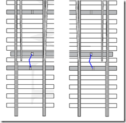 revealed some verbal descriptions on a blog, but no pictures. I know it’s just three bends in a piece of wire, but someone should really do a video or something. For now, the diagram to the left will have to do. The idea is simple: moving the turnout from right to left causes compression in the spring (the blue line) until the throw reaches the midpoint. At the midpoint, the spring is under maximum compression. Further movement to the left will release compression on the spring, causing the points to snap to the left when the throw reaches the midpoint. The same compression occurs as the points are moved back to the right, causing the points to snap to the right once the throw moves past the midpoint on the right side. Since the compression tends to release itself once the throw is moved “over the center point,” these devices are called “over-center springs" or "center-over springs.” Below is a YouTube video on how I made center-over springs for my Atlas turnouts.
When it comes to turnout control, there’s a whole host of ways to accomplish the task: Tortoise machines, servos, ground throws, latch-bolt throws, solenoid machines, finger-flick, pushrods…and then there’s the combinations of these methods! To simplify things, I like to categorize these in terms of Electronic vs. Manual and Under-table vs. Topside-mount. Here’s the breakdown on how those technologies fit into my grid:
| Electronic | Manual | |
| Under-table |
|
|
| Topside Mount |
|
|
I initially bought some Caboose Industries ground throws, but their large size compromised the appearance of the code 55 track. Why go to the trouble of near-scale track only to butcher the look with an oversize ground throw? I would have been better off to use Peco code 55 and lived with the European tie spacing. While there have been some really good ideas to disguise the CI throw’s oversize appearance, I didn’t think this would work since my spline roadbed would basically leave the throws unsupported. I tried using electric toggle switches with linkages on my test bed layout. While simple enough, I’ve had some problems with the toggle throw being longer than the turnout throw. The turnouts on my test bed layout were soldered together, so they were able to handle the stress. I feared that the Atlas code 55 turnouts might not fare so well and there’s still that whole mounting thing. That left me with the finger-flick method with either a center-over spring or a friction pad. I tried doing a friction pad on the bottom of the throwbar, but worries of what would happen once the friction pad wore down kept me from pursuing this route. Still the friction pad is a great idea and is probably something I’ll consider again.
So a center-over spring it is! Atlas code 55 turnouts, unlike their Peco and Micro Engineering counterparts, do not have a center-over spring. No problem. I’ll just make one. Surely someone on the internet has a “how-to” to guide me. A search
 revealed some verbal descriptions on a blog, but no pictures. I know it’s just three bends in a piece of wire, but someone should really do a video or something. For now, the diagram to the left will have to do. The idea is simple: moving the turnout from right to left causes compression in the spring (the blue line) until the throw reaches the midpoint. At the midpoint, the spring is under maximum compression. Further movement to the left will release compression on the spring, causing the points to snap to the left when the throw reaches the midpoint. The same compression occurs as the points are moved back to the right, causing the points to snap to the right once the throw moves past the midpoint on the right side. Since the compression tends to release itself once the throw is moved “over the center point,” these devices are called “over-center springs" or "center-over springs.” Below is a YouTube video on how I made center-over springs for my Atlas turnouts.
Saturday, November 14, 2009
DCC Controls for the HOG
Among all of the construction decisions, I've been contemplating how I'm going to control this layout. DCC is a foregone conclusion as it's the best way to get control of the locomotive (and all of my locomotives are already DCC-equipped). I've got a Digitrax Radio Super Chief that I purchased with the intention of using with an N-trak group (more on that below), but this system is overkill for a layout of this size and the only other modeler in my local area is an NCE user. The NCE PowerCab is the best option for a layout of this size, but my wife is liking the idea of using her iPod Touch as a throttle, so the ESU Ecos system has been getting alot of looks as well.... The Digitrax Radio Super Chief is a fantastic system, and when I bought it, I had several HO locomotives that had all of the bells and whistles (or the sounds, at least) and I needed the many, many functions that the Digitrax DT400R could perform. I've since sold this HO equipment and my N scale equipment doesn't need such a fancy control system. However, I noticed that many of the Ntrak clubs in the Dallas-Fort Worth area were avid Digitrax users and the Super Chief makes a nice system for an N-trak club. With that in mind, I built an "N-trak box". Here's what it looks like:


The box is built out of aspen plywood and measures 19" x 10" x 10". While there may be some wasted space, it ain't much! The top photo shows the front of the box. On the front is a lockable case latch so a small padlock can be applied to the case to keep little hands out when it's time to go to lunch or peruse the train show. The second photo shows the end where a large computer fan draws in air and pushes it across the transformers and the booster. On the backside (third photo), you can see the piano case hinge for the box lid, the exit hole for the cooling air, and the standard computer plug that connects to the power supply. Using the removable power cord makes it very easy to transport. The last picture shows the business end with the Digitrax UR91 radio throttle receiver and four Cinch-Jones plugs. The Cinch-Jones connectors are the Ntrak standard, so this box can quickly be connected to any Ntrak layout.


Opening the box, there's a programming track and a tray to hold all of the throttles, power cable, and connector cable. This tray is also a safeguard against curious little hands that might find their way into the box.

Removal of the tray reveals the guts of the system: The DCS100 booster, the UR91 radio throttle receiver, and the PM42 power manager (all on the right). The booster is attached with heavy-duty velcro just in case it needs to be removed. The UR91 allows Digitrax simplex radio throttles to be used. The PM42 is particularly necessary for Ntrak layouts since it allows individual circuit breaker detection. This way, a short on one track doesn't cause a system crash and everyone else can keep running trains while the short is found. On the left, there are a couple of fuses and a circuit breaker for the power supply. Just plugging in the power cord does not power up the transformers. The switch on the far left has to be thrown first. Even that does not power up the booster; that's the purpose of the other switch. All exposed wiring on the right side of the box is either 12V or 16V, so there's no real shock hazard. Even at this level, I didn't want there to be any chance of a child getting shocked. Hopefully, someone will have spotted the little tike by the time he/she gets this far!!

Removing the partition and lifting the cover that contains the power switches and the circuit breakers shows the transformers. The terminal blocks on the left carry 110V power, so it's a good idea to have the box unplugged before even opening this side. The fan is a 110V fan, so it runs directly off the input power. The large transformer powers the booster, while the two smaller transformers provide power to the UR91 and the PM42.
And that's it! All in all, it's about the best way I've seen to make a full DCC system truly portable. Putting the system in a box sure cuts down on the clutter associated with the Digitrax system, so this might be a good idea for any Digitrax user. I hope these ideas are of some use to you...


The box is built out of aspen plywood and measures 19" x 10" x 10". While there may be some wasted space, it ain't much! The top photo shows the front of the box. On the front is a lockable case latch so a small padlock can be applied to the case to keep little hands out when it's time to go to lunch or peruse the train show. The second photo shows the end where a large computer fan draws in air and pushes it across the transformers and the booster. On the backside (third photo), you can see the piano case hinge for the box lid, the exit hole for the cooling air, and the standard computer plug that connects to the power supply. Using the removable power cord makes it very easy to transport. The last picture shows the business end with the Digitrax UR91 radio throttle receiver and four Cinch-Jones plugs. The Cinch-Jones connectors are the Ntrak standard, so this box can quickly be connected to any Ntrak layout.


Opening the box, there's a programming track and a tray to hold all of the throttles, power cable, and connector cable. This tray is also a safeguard against curious little hands that might find their way into the box.

Removal of the tray reveals the guts of the system: The DCS100 booster, the UR91 radio throttle receiver, and the PM42 power manager (all on the right). The booster is attached with heavy-duty velcro just in case it needs to be removed. The UR91 allows Digitrax simplex radio throttles to be used. The PM42 is particularly necessary for Ntrak layouts since it allows individual circuit breaker detection. This way, a short on one track doesn't cause a system crash and everyone else can keep running trains while the short is found. On the left, there are a couple of fuses and a circuit breaker for the power supply. Just plugging in the power cord does not power up the transformers. The switch on the far left has to be thrown first. Even that does not power up the booster; that's the purpose of the other switch. All exposed wiring on the right side of the box is either 12V or 16V, so there's no real shock hazard. Even at this level, I didn't want there to be any chance of a child getting shocked. Hopefully, someone will have spotted the little tike by the time he/she gets this far!!

Removing the partition and lifting the cover that contains the power switches and the circuit breakers shows the transformers. The terminal blocks on the left carry 110V power, so it's a good idea to have the box unplugged before even opening this side. The fan is a 110V fan, so it runs directly off the input power. The large transformer powers the booster, while the two smaller transformers provide power to the UR91 and the PM42.
And that's it! All in all, it's about the best way I've seen to make a full DCC system truly portable. Putting the system in a box sure cuts down on the clutter associated with the Digitrax system, so this might be a good idea for any Digitrax user. I hope these ideas are of some use to you...
Saturday, November 7, 2009
Adding the Fascia
Once the glueshell dried, I measured from the bottom of the benchwork to the top of the glueshell scenery at the layout edges. Just under 6” was the longest measurement, so I cut a 4x8 sheet of Masonite into 6” strips and attached them to the sides of the layout with clamps to temporarily hold them in place. Using a felt pen, I marked off the land contours by tracing along the joint between the glueshell and the fascia board. Cutting along the lines with a jigsaw yielded a nice fascia piece that matched to land contours:

You can see the holes that were drilled to allow the clamping bolts to pass through. I forgot to do this on one section before I attached them to the layout. Let’s just say that it really helps to pay attention to detail at this point! Once the contours were shaped, it was time to attach them to the layout with wood glue and clamps:


You’ll notice that I let the ends hang out over the corners of each layout section. These can be cleaned up with a flush-trim bit in a Roto-Zip after the glue dries.

One advantage of allowing the ends to hang out a bit is that you have a surface to leverage if the corners don’t come out EXACTLY square. I had this happen on the end piece in the photo below where I was lacking a 1/16” being flush with the adjacent piece at the corner. Using a bungee strap and the weight of the layout, I was able to pull against those long ends to take that 1/16” out and get a nice, flush fit:

After trimming with the Roto-Zip, here’s the layout with the fascia installed:


I also had to do a bit of cleanup with the flush-trim bit at the layout joints since some of my marks didn’t match up exactly. If you haven’t used one of these bits in a Roto-Zip or a router, they make quick work of the problem of cutting a corner piece exactly to length. I highly recommend giving one a try!
Glue Shell Scenery – Comments now that it’s dried…
In my last post, I only had one layer of glueshell scenery down and I was switching from diluted ModPodge to full-strength Elmer’s GlueAll. My hope was that the full-strength Glue-All, coupled with the second layer of paper, would create a nice rigid scenery shell. Unfortunately, that plan didn’t come together exactly like I’d hoped! The full-strength GlueAll is still pretty rubbery, flexible stuff after it dries. The second layer of paper did help to make things a bit more rigid, but not nearly as hard as a plaster shell. This can be a good thing, though. My layout is intended to be semi-portable. Scenery that has some give to it will be less likely to be punctured or cracked as things get moved around.
I had some places where the paper shrunk as it dried, which created some interesting landforms. By far, the glueshell did the best job in the places where it was well-supported by the benchwork. It’s not a good idea to try to cover vast expanses of unsupported areas with cheesecloth, paper and glue. If you’ve got this situation, either use a stiffer plastic or even metal screen in place of the cheesecloth or use a stiffer medium than the glue (plaster is a good example). Hindsight being 20/20, I really wished I’d used undiluted PVA (wood glue) as my medium throughout. It’s $30 a gallon at the local big box store, but it dries much stiffer than either ModPodge or GlueAll.
Good news is, I’ve got the opportunity to give this a try: I’ll be using Titebond 3 to attach the glueshell to the fascia; an area where a good, stiff connection is critical. I’ll let you know the outcome. I still love the glueshell scenery and I’ll continue to use it, but I did learn a lesson about unsupported scenery this time around…
Been a while….
I had originally thought that this blog would be a great way to 1) share my experiences in model railroading and 2) to keep myself moving forward on the railroad since folks might be following along. The reality is that blogging takes some work to be worth a flip. You need pictures that are of decent quality and help tell the story. Unless you’re like my sister-in-law, you also need time to think through the post and to write it well. The aforementioned sister-in-law is able to put together well-written posts in a matter of 30 minutes or so…I just don’t have her verbal skills!
SO…rather than spend an inordinate amount of time blogging, I decided to focus my efforts on getting the layout done. Since the last post, I’ve laid up another layer of glueshell scenery using full-strength Elmer’s GlueAll, added the layout fascia, laid the cork roadbed, made some decision regarding turnout linkages and begun to solder together some of the “turnout junctions.” I’ll address the outcomes of each of these activities in separate posts (to make them easier to follow). The great thing about this approach is that my modeling time is put to maximum effect and progress is made. The bad thing about this approach is that my blog goes long periods without being updated. I’d rather have a model railroad than a really nice blog, so the trade-off has been a good one…
Subscribe to:
Posts (Atom)